Restorative Dentistry
Digital Technologies
for Restorative Dentistry
Dr. Zaid Abu Zaid
From scan to same-day restoration
The route
One digital thread
Four chapters, one continuous flow of data: from the mouth, to the file, to the restoration.
Chapter oneDigitization of oral structures
Chapter twoCAD/CAM
Chapter threeVirtual design
Chapter fourThe virtual patient
Chapter one
Digitization of oral structures
Digitization means optically scanning oral structures, either directly or indirectly.
Direct digitization
The intraoral scanner
- Faster than a conventional impression
- More comfortable for the patient
- More convenient to handle and to send
- Accuracy now comparable to polyvinyl siloxane (PVS) impressions
Key pointSuitable for single-tooth restorations and short-span fixed dental prostheses (FDPs).
Starting the scan: the wand held parallel to the occlusal plane, the first data appears
One prepared tooth, five angles: the proximal walls are captured
Limitation 1
Errors accumulate over long scans
The scanner stitches many small images. Each join carries a tiny error. Over a full arch the errors add up.
ExplainerShort span = few joins = accurate. Full arch = many joins = drift.
Key pointDistortion grows with the length of the scanned area, not with the scanner alone.
A full arch needs one long continuous path: many more joins
The manufacturer's own advice: split the full arch into segments
Limitation 2
Movable tissue cannot be captured
Reproduced accurately, with accuracy similar to conventional impression techniques.
Its shape changes during scanning, so the captured outline is unreliable. This is seen with different scanner systems, so it relates to tissue movement, not to one scanner.
Key pointLong edentulous areas that need border molding: intraoral scanning is not always predictable.
Accuracy
It depends on the patient and on the operator
Patient factors
Tooth type and interdental space
Posterior teeth are harder to scan accurately: more complex anatomy and harder access.
Most scanners drift toward the buccal side as the scan moves posteriorly. The i500 drifted toward the lingual side.
Under 3 mm: errors occur and vary with scanning direction. Over 3.5 mm: no significant effect.
Where data are missing the software may interpolate, creating artificial bulges at the margin (positive deviations).
Key pointMore interdental space = better access = better accuracy.
Patient factors
Arch width and the palate
Trueness: not significantly affected. Precision: decreases as arch width increases, so more variation between repeated scans.
Intermolar width: wider generally meant larger discrepancies. The i500 was worst at both extremes, narrowest and broadest.
Higher trueness and precision when the palate is not included in the maxillary scan.
A higher vault meant more discrepancy, though the difference was not statistically significant.
Key pointWider arch = lower precision. Exclude the palate when you can.
Patient factors
Wetness and existing restorations
Water changes how light is reflected from the surface, so surface detail is lost. Keep the field as dry as possible.
Retract, rinse and dry the field before the scan
Accuracy varies with material, translucency and surface finish. In zirconia, polished surfaces gave higher trueness than glazed.
Scanning powder cuts reflections from highly reflective restorations and may shorten scan time. Apply a thin, uniform layer when needed.
Matting powder applied as a thin, even layer
Patient factors
The preparation itself
- Sharp angles, rough surfaces, irregular shapes: lower accuracy
- Full-coverage preparations scan better than intracoronal (inlay) preparations
- Higher convergence angle for crowns and higher divergence angle for inlays: better
- Undercuts below the height of contour = shadow regions = missing data
- Deeper pulpal or gingival floors: lower accuracy
- Finish line: supragingival scans best. Equigingival and subgingival had the lowest accuracy and the most deficiencies
Key pointAnterior, shallow and supragingival is easy. Posterior, deep and subgingival is hard.
Operator factors
System, head size, calibration, distance
Every scanner differs in hardware and software, yet all provide a reliable alternative to conventional impressions.
Small head: better access with limited opening. Large head: potentially higher accuracy.
Calibrate daily before scanning. iTero Element and TRIOS 5 have integrated self-calibration.
No single optimal distance. Follow the manufacturer's recommended distance and focal depth.
Operator factors
Temperature, lighting, experience, pattern
Ambient temperature changes can knock the scanner out of calibration. Calibrate at the start of each workday.
Best at about 1000 lux, normal room light: chair light off, ceiling light on. Implant scan bodies prefer about 500 to 800 lux.
Experienced operators scan more accurately. Newer systems depend less on operator experience.
Different scanning paths give different accuracy. Follow the sequence provided by the manufacturer.
The manufacturer's anterior sequence: one sweep across the anterior segment
Operator factors
Cut, rescan, overlap: each one costs accuracy
- Removing and rescanning an area introduces errors when the new data is merged with the existing data
- The larger the number and the diameter of the mesh holes, the greater the loss of accuracy
- Overlapping areas during rescanning also lowered accuracy
Key pointScan it right the first time.
The other road
Indirect digitization
When direct scanning is not suitable, scan the impression or the stone cast on a laboratory scanner.
- Laboratory scanners are more accurate than intraoral scanners
- But the impression and the cast can distort, during making and during pouring
- Preferred for full-arch work where cross-arch accuracy is critical
Key pointFinal accuracy = quality of the original impression or cast.
Indirect digitization
Laboratory scanners
- Early scanners: a fixed light source, one fixed angle
- Modern scanners: the object or the optics move, capturing many angles and more detail
- Limitation: movement is still more limited than a hand-held scanner, so undercuts and interproximal areas can be missed
- Solution: two-step scanning. Rescan the missed area separately and merge it
Key pointLimited movement = missed areas = two-step scanning.
Indirect digitization
Scanning the impression itself
- Possible when the impression is shallow, has no major undercuts in critical areas, and key areas are accessible
- Posterior areas of impressions may scan more easily than anterior areas
- Triple-tray impressions can be scanned
- Virtual models from scanned impressions have clinically acceptable accuracy
Key pointA stone cast is still needed for physical try-in or adjustment.
Chapter one
Choose the road by the case
- Single tooth
- Short-span FDP
- Fast and comfortable
- Fewer joins, less drift
- Full arch needing cross-arch accuracy
- Removable cases with border molding
- When the mouth cannot be scanned well
- Accuracy inherited from the impression
Bottom lineChoose the road by the case, not by the gadget.
Chapter two
CAD/CAM
Digital restorative engineering: design the restoration on screen, then manufacture it in the room.
Definition
What CAD/CAM means
Computer-Aided Design and Computer-Aided Manufacturing: software and hardware that digitize the impression, model the restoration in 3D and fabricate it with micrometric precision.
OriginIt began in the 1980s with Dr. Francois Duret and the CEREC system. It replaces elastomeric impressions and manual waxing with a digital workflow.
The core architecture
Three stages: acquire, design, fabricate
Intraoral scanners capture 3D optical coordinates of the prepared teeth and the soft tissue, producing high-density point clouds and open STL or PLY models.
The software analyses dynamic occlusal clearance, the emergence profile, the margin fit line and the contact parameters in real time.
Multi-axis CNC milling units or stereolithography 3D printers shape monolithic ceramic, zirconia or resin blocks into the restoration.
The chairside mill carving the restoration out of a block
The digital clinical pathway
No stone model, no transit time
Standardised reduction with a clear supragingival or equigingival finish line.
Reduction with the bur, finish line kept clear
Both arches and the interocclusal registration, captured in minutes.
Bite registration: tip held distal, short up and down passes
A biogeneric algorithm proposes the morphology from the adjacent anatomy.
Fast furnace firing brings the restoration to full strength and final shade.
Major clinical advantages
What the patient gets, what the restoration gets
A crown in one visit, sixty to ninety minutes, with no temporary and one injection.
The permanent restoration cemented in the same visit
A clean optical camera replaces the tray and the putty.
Preparation and final placement happen in the same appointment.
Computer-controlled margins: a tighter fit and fewer leaks.
Factory-pressed zirconia and ceramic blocks with zero porosity.
If a crown breaks, re-mill it from the stored file, immediately.
Bottom lineOne visit, one injection, one file that never expires.
At a glance
Traditional versus CAD/CAM
Feature
Traditional method
CAD/CAM digital method
Impression
Putty tray, often triggers gagging
3D optical scan: fast, comfortable, clean
Appointments
Two visits, two to three weeks apart
Single visit, finished in one to two hours
Temporary tooth
Needed for weeks, can break or fall off
None needed: the permanent tooth is placed today
Remakes and duplicates
Repeat the full impression and wait weeks
Instant re-mill, straight from the saved file
Challenges
What CAD/CAM still costs you
- High initial cost: scanners, milling machines and CAD licences, forty thousand to over one hundred and twenty thousand US dollars
- Learning curve: training in optical scanning, 3D software and digital occlusion
- Moisture and blood: the scanner cannot see through them, and margins under swollen gums need cord retraction
- Bur size limits: burs have a minimum thickness, so very small internal crevices may be over-milled
Key pointThe machine cannot cut a detail finer than the bur that cuts it.
Chapter three
Virtual design
Computer-aided design: the software proposes, the clinician decides.
Computer-aided design
The automatic proposal
Most CAD software proposes an initial design from the selected tooth shape, the adjacent teeth, the opposing teeth and the surrounding structures.
- Single restorations: the proposal is usually satisfactory
- Multiple restorations or extensive FDPs: more adjustment by the operator
Key pointSingle is predictable. Multiple means more work.
The software draws the restoration into the gap between the neighbours
Before fabrication
Evaluate the design on real records
Digital records are used to check and refine the proposed restoration before it is made:
- Scanned diagnostic models
- Interim or provisional restorations
- Intraoral mock-ups
- Other trial restorations
Key pointEvaluate on records, adjust, then fabricate.
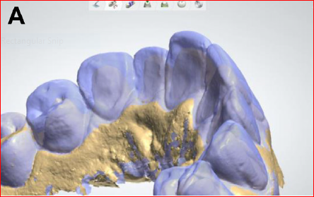
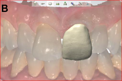
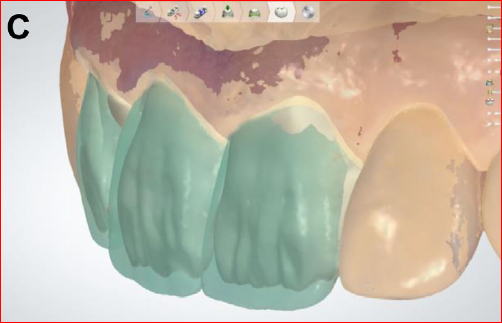
Design references: scanned models and trial restorations superimposed on the proposal
The rule that does not move
CAD makes the design faster.
It does not change the design.
Computer-aided design is a tool. The biological, functional and mechanical principles of conventional prosthetic design still apply, unchanged.
Chapter four
The virtual patient
Virtual simulation technologies: virtual smile design and the virtual articulator.
Key pointVirtual simulation means better esthetic and functional planning.
Virtual smile design
From one angle to the whole face
Lines and virtual calipers drawn on facial photographs, then a diagnostic wax-up to move the plan onto a physical model.
Accuracy depended on the operator turning a 2D drawing into a 3D design. Limitation: one viewing angle only.
3D facial scanning lets the clinician judge esthetics from many angles, so the effect of the plan on the whole face is visible.
Expected to grow, because smartphone applications can now capture a 3D face. Useful for migrated, malposed or damaged teeth.
Key point2D shows one angle. 3D shows the whole face.
Virtual patient
The virtual articulator
Software that reproduces the interarch relationship and simulates jaw movements digitally, so occlusion and function can be checked before anything is fabricated.
Mounted arches moving through the excursions inside the software
Records the real movement paths of the mandible with an electronic jaw registration system. Useful in complex cases. Rarely used: extra equipment, more complexity, and many dentists are unfamiliar with it.
Electronic jaw registration: paraocclusal tray, marker, head frame
Calculates the movement paths from values entered into the software.
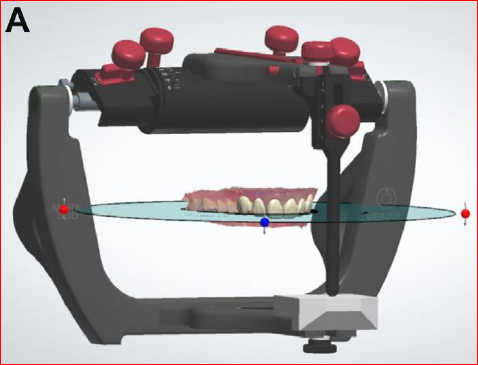
Getting the jaws into the software
Virtual facebow transfer
To use a virtual articulator, the real 3D position of the maxilla and the mandible must be transferred into it. That transfer is the virtual facebow.
Arbitrary mounting
Cephalometric radiograph
3D facial scan with extraoral markers
Photographs converted to a 3D scan
Digital axiography
Stereophotogrammetry
Standardised extraoral photographs
CBCT-based methods
Evidence
Accuracy and clinical use
Clinically acceptable and comparable to mechanical articulators. Influenced by alignment method, arch length, scanner type, articulation method, the algorithm and the use of a mechanical articulator.
In vitro, with a mathematically simulated articulator: accuracy similar to a mechanical articulator, with deviations under one hundred micrometres.
An additional diagnostic and planning tool, not yet a replacement for the mechanical articulator. Especially useful when the vertical dimension of occlusion changes.
Dynamic contact marks appearing on the restoration during simulated movement
Hsu MR, Driscoll CF, Romberg E, et al. Accuracy of dynamic virtual articulation. J Prosthodont 2019;28(4):436–443. · Lepidi L, et al. J Prosthodont 2021;30(1):24–35.
Finale
The virtual patient: everything connected
1 / 7Intraoral scan
Take-home
Five things to carry out of this room
- 1Intraoral scanning is accurate for single units and short spans. Errors accumulate over long spans and over mobile tissue.
- 2Accuracy is controllable: a dry field, good access, supragingival margins, daily calibration, about 1000 lux, one clean pass.
- 3Indirect digitization still wins for full-arch work where cross-arch accuracy is critical.
- 4CAD/CAM gives same-day, precise, repeatable restorations. The principles of design do not change.
- 5The virtual patient, smile design plus articulator plus facebow, is an additional planning tool. Not yet a replacement.
Thank you
Dr. Zaid Abu Zaid
Digital Technologies for Restorative Dentistry
References
Hsu MR, Driscoll CF, Romberg E, et al. Accuracy of dynamic virtual articulation: trueness and precision. J Prosthodont 2019;28(4):436–443.
Lepidi L, et al. J Prosthodont 2021;30(1):24–35.
Source lecture material adapted for this presentation.
Hsu MR, Driscoll CF, Romberg E, et al. Accuracy of dynamic virtual articulation: trueness and precision. J Prosthodont 2019;28(4):436–443.
Lepidi L, et al. J Prosthodont 2021;30(1):24–35.
Source lecture material adapted for this presentation.